I have just finished upgrading my LGB 1045 to sound. My locomotive had originally been converted to digital at the factory, but this write up might be useful for analog locomotives too after converting the motor block to 4-wire.
LGB 2045 RhB #205 GE 2/4 Upgrade to Sound (January 2022)
Parts Used:
Massoth 8154001 eMotion L Driving Decoder
Massoth 8212100 eMotion S Sound Decoder (Sound Project 823X045 v. 4.10)
Massoth 8242010 Volume Control
Massoth 8242020 Reed Switch Board
Visaton FRS-5 8 ohm Loudspeaker
2 each DPST Toggle Switches (on-on)
I acquired this engine in 2018. It was an early digital version, factory converted and signed by Eberhard Richter. The motor block had been modified to 4-wire and an older 55021 decoder had been installed. “D” stickers had been attached to the motor block and printed on the end of the box
This was easy to work on! There was plenty of room inside for modifications and the dummy pantographs allowed the roof to be easily removed. There are 6 screws located underneath the pressed-on catwalks for removing the roof.
Tons of room allow for a high-quality speaker and large rectangular openings for the drive mechanism in the floor are sufficient for the sound to exit. I used a Visaton FRS-5 loudspeaker mounted it in a 3D printed PETG enclosure screwed to the front weight
My initial plan was to replace the older LGB 55021 decoder with a Massoth L driving decoder and connect the Massoth S sound decoder via the SUSI bus. However, the L decoder I had on hand was an older version (1.0) that would not support SUSI, and could not be upgraded
I ordered a new L decoder and with the Massoth service tool was able to read and write CVs flawlessly on both decoders - if they were connected to track power individually. However, when I connected the S decoder to the L decoder via SUSI I got many read and write errors.
I contacted Massoth about the issue and was recommended to connect both decoders to track power and use the program lock CVs to address the decoders separately. Unfortunately, that didn’t s work for me either.
I went back to the tried and true method of toggle switches to isolate the decoders from each other when programming. From previous experience I chose to use double pole switches to simultaneously cut out both the T+ and T- leads. This seems to be the only way to eliminate interference between decoders (I assume because the DCC track voltage is a form of AC). Once done, I could read and write all CVs on either decoder with no problems
I mounted the S decoder in a bracket on the rear weight, with the L decoder mid-compartment in the original 55021 brackets.
I mounted the volume control in a suitable location on the right side of the center compartment with the volume knob accessible below. This was plugged into the appropriate socket on the S decoder
I added a Massoth reed switch board using a 3D printed PETG protective housing. The switches were mounted to the cover plate for the front bogie pivot. A hole drilled in the space next to the pivot point allowed the switch wires to run up to the decoder.
The reed contacts needed to be soldered to pads on the back of the sound decoder, with the center brown wire going to Dec- and the other two black wires going to K1 and K2.
I found a suitable location for the two toggle switches on the right side of the locomotive. Brown and white wires were run from the T- (brown) and T+(white) pins on top of the motor block to the center terminals on the toggle switches. The brown and white leads from the decoders were soldered to one of the “on” positions on each switch respectively, so that none, either, or both of the decoders could receive track powe
There are 3 lights on either end of the locomotive. The upper light and lower right light on each end are connected to the regular headlight outputs on the L decoder and come on with the direction of travel. The lower left lights on each end are connected to the A1 function output of the decoder and are always on no matter the travel direction. The lights are all 5 volts so the decoder must be programmed accordingly. All the lights are turned on or off with the light button (f9) on the controller.
Once everything was complete, the locomotive was placed on a programming track to set some important CV’s.
eMotion L
CV1 set to 26 (locomotive address 26)
CV29 set to 22
Bit0=0 “standard driving direction”
Bit1=1 “28/128 speed steps”
Bit2=1 “digital and analog operation”
Bit4=1 “programmable speed curve”
Bit5=0 “short address”
CV50 set to 6 (light dimming value of ~4.5 volts)
CV51 set to 128 (front light on when going forward only)
CV52 set to 64 (rear light on when going backwards only)
CV53 set to 6 (dimming value of ~4.5 volts for light connected to A1 output)
CV54 set to 0 (switch A1 output with light key (f9) only)
eMotion S
CV1 set to 26 (locomotive address 26)
CV29 set to 22
Bit0=0 “standard driving direction”
Bit1=1 “28/128 speed steps”
Bit2=1 “digital and analog operation”
Bit4=1 “programmable speed curve”
Bit5=0 “short address”
CV190 set to 1 (sound 1 triggered by reed 1)
CV191 set to 2 (sound 2 triggered by reed 2)
CV200 set to 255 (total volume controlled by potentiometer)
Figure 1: Original Box Showing “D” Designation
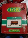
Figure 2: Motor Block Showing “D” Designation
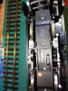
Figure 3: Original LGB 55021 Decoder
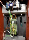
Figure 4: FRS-5 In 3D Printed Enclosure
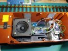
Figure 5: Volume Control Pot from Below
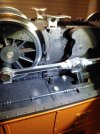
Figure 6: Volume Control Pot from Inside
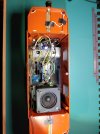
Figure 7: 3D Printed Reed Switch Cover
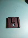
Figure 8: With Bogie Pivot Cover
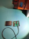
Figure 9: Location for Reed Switch
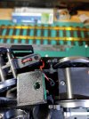
Figure 10: Reed Switches Mounted
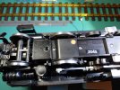
Figure 11: Toggle Switches from Below
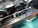
Figure 12: Toggle Switches from Within
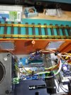
Figure 13: Reed Switch Leads Soldered to S Decoder
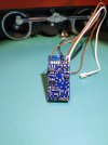
Figure 14: Completed Interior Electronics
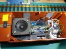
Figure 15: Right Side View of Locomotive
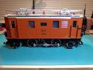
Figure 16: Headlights in Forward Motion
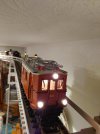
Figure 17: Headlights in Reverse Direction
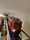
Figure 18: Labelled Controls
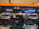
LGB 2045 RhB #205 GE 2/4 Upgrade to Sound (January 2022)
Parts Used:
Massoth 8154001 eMotion L Driving Decoder
Massoth 8212100 eMotion S Sound Decoder (Sound Project 823X045 v. 4.10)
Massoth 8242010 Volume Control
Massoth 8242020 Reed Switch Board
Visaton FRS-5 8 ohm Loudspeaker
2 each DPST Toggle Switches (on-on)
I acquired this engine in 2018. It was an early digital version, factory converted and signed by Eberhard Richter. The motor block had been modified to 4-wire and an older 55021 decoder had been installed. “D” stickers had been attached to the motor block and printed on the end of the box
This was easy to work on! There was plenty of room inside for modifications and the dummy pantographs allowed the roof to be easily removed. There are 6 screws located underneath the pressed-on catwalks for removing the roof.
Tons of room allow for a high-quality speaker and large rectangular openings for the drive mechanism in the floor are sufficient for the sound to exit. I used a Visaton FRS-5 loudspeaker mounted it in a 3D printed PETG enclosure screwed to the front weight
My initial plan was to replace the older LGB 55021 decoder with a Massoth L driving decoder and connect the Massoth S sound decoder via the SUSI bus. However, the L decoder I had on hand was an older version (1.0) that would not support SUSI, and could not be upgraded
I ordered a new L decoder and with the Massoth service tool was able to read and write CVs flawlessly on both decoders - if they were connected to track power individually. However, when I connected the S decoder to the L decoder via SUSI I got many read and write errors.
I contacted Massoth about the issue and was recommended to connect both decoders to track power and use the program lock CVs to address the decoders separately. Unfortunately, that didn’t s work for me either.
I went back to the tried and true method of toggle switches to isolate the decoders from each other when programming. From previous experience I chose to use double pole switches to simultaneously cut out both the T+ and T- leads. This seems to be the only way to eliminate interference between decoders (I assume because the DCC track voltage is a form of AC). Once done, I could read and write all CVs on either decoder with no problems
I mounted the S decoder in a bracket on the rear weight, with the L decoder mid-compartment in the original 55021 brackets.
I mounted the volume control in a suitable location on the right side of the center compartment with the volume knob accessible below. This was plugged into the appropriate socket on the S decoder
I added a Massoth reed switch board using a 3D printed PETG protective housing. The switches were mounted to the cover plate for the front bogie pivot. A hole drilled in the space next to the pivot point allowed the switch wires to run up to the decoder.
The reed contacts needed to be soldered to pads on the back of the sound decoder, with the center brown wire going to Dec- and the other two black wires going to K1 and K2.
I found a suitable location for the two toggle switches on the right side of the locomotive. Brown and white wires were run from the T- (brown) and T+(white) pins on top of the motor block to the center terminals on the toggle switches. The brown and white leads from the decoders were soldered to one of the “on” positions on each switch respectively, so that none, either, or both of the decoders could receive track powe
There are 3 lights on either end of the locomotive. The upper light and lower right light on each end are connected to the regular headlight outputs on the L decoder and come on with the direction of travel. The lower left lights on each end are connected to the A1 function output of the decoder and are always on no matter the travel direction. The lights are all 5 volts so the decoder must be programmed accordingly. All the lights are turned on or off with the light button (f9) on the controller.
Once everything was complete, the locomotive was placed on a programming track to set some important CV’s.
eMotion L
CV1 set to 26 (locomotive address 26)
CV29 set to 22
Bit0=0 “standard driving direction”
Bit1=1 “28/128 speed steps”
Bit2=1 “digital and analog operation”
Bit4=1 “programmable speed curve”
Bit5=0 “short address”
CV50 set to 6 (light dimming value of ~4.5 volts)
CV51 set to 128 (front light on when going forward only)
CV52 set to 64 (rear light on when going backwards only)
CV53 set to 6 (dimming value of ~4.5 volts for light connected to A1 output)
CV54 set to 0 (switch A1 output with light key (f9) only)
eMotion S
CV1 set to 26 (locomotive address 26)
CV29 set to 22
Bit0=0 “standard driving direction”
Bit1=1 “28/128 speed steps”
Bit2=1 “digital and analog operation”
Bit4=1 “programmable speed curve”
Bit5=0 “short address”
CV190 set to 1 (sound 1 triggered by reed 1)
CV191 set to 2 (sound 2 triggered by reed 2)
CV200 set to 255 (total volume controlled by potentiometer)
Figure 1: Original Box Showing “D” Designation

Figure 2: Motor Block Showing “D” Designation

Figure 3: Original LGB 55021 Decoder

Figure 4: FRS-5 In 3D Printed Enclosure

Figure 5: Volume Control Pot from Below

Figure 6: Volume Control Pot from Inside

Figure 7: 3D Printed Reed Switch Cover

Figure 8: With Bogie Pivot Cover

Figure 9: Location for Reed Switch

Figure 10: Reed Switches Mounted

Figure 11: Toggle Switches from Below

Figure 12: Toggle Switches from Within

Figure 13: Reed Switch Leads Soldered to S Decoder

Figure 14: Completed Interior Electronics

Figure 15: Right Side View of Locomotive

Figure 16: Headlights in Forward Motion

Figure 17: Headlights in Reverse Direction

Figure 18: Labelled Controls

-
3
-
1
- Show all

