I got one of these recently, the latest version model 37568. There are seven other models 3756x representing variations on BR 110 diesels including BR 112, BR 114 and others. These instructions would apply to any of these, and probably the "Harzkamel" BR 199 narrow gauge variants (3754x) as well but as I don't have one I can't be sure.
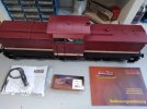
They come as analogue DC models with 2 motors and directional lighting, but provide for upgrade to DCC, sound, and extra lighting options (red rear lights). There are PIKO upgrade options you can buy, or you can do your own thing. I prefer Massoth so I have used a Massoth XL decoder and a Massoth S sound module, mainly because I had a spare one. PIKO used to rebadge Massoth XL decoders as their own, so the earlier instructions they provide can be applied to installing the Massoth XL. For sound they used to rebadge the Uhlenbrock SUSI sound modules which are "plug and play", but more recently they have produced their own motor and sound decoders. I did however use their light options kit (#36016).
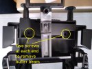
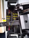
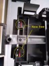
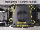
To open up the loco (i.e. remove the body shell), there are eight screws, four of which hold on the buffer beams which you then have to unclip as they have a slot and lug holding the body shell in place at the ends. These are larger screws, the other four are quite small and hard to locate, you have to swivel the bogies to access them. I think once these small screws are undone you could possibly leave them out as no way will the body separate once the buffer beams are locked in.
Once open you can remove the analogue circuit board (two diodes for the directional lighting!) making note of which wires go where, preferably labelling them before you remove them. Here's a rundown of the eight connections:
1 - track- (black)
2 - motor+ (blue)
3 - rear lights (yellow)
4 - unused
5 - +ve common (black)
6 - front lights (yellow)
7 - motor- (red)
8 - track+ (black)
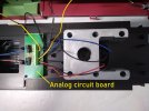
Here's how they map to the nine Massoth XL connectors (right hand side):
A1 - unused
LI-H - rear lights (yellow)
M- - motor- (red)
GL- - track- (black)
GL+ - track+ (black)
M+ - motor+ (blue)
LI-V - front lights (yellow)
GRD - unused
+22 - +ve common (black)
Given that there are three black wires and two yellow wires there is scope for error! Be especially careful of the black wire for the +ve common, you don't want to be accidentally shoving track power into that connection. It is easy to identify the +ve common as it has resistors hidden in heat shrink to protect the LED lights from current overload.
That's the existing wires covered, now to add the "additional lighting" LEDs from accessory pack 36016. They are wired in pairs for front and back, with brown wires (-ve) and (more) black wires (+ve). The LED lights plug into the holes in the light harness at each end of the loco. There is a handy "two into one" short piece of cable that allows you to plug in the two +ve black wires into one, which makes it much easier to connect to the decoder.
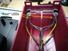
You could plug these into the LI-V (front) and LI-H (rear) light connections on the XL, in reverse of the white directional lights, but that would mean the rear lights would always be on. This would not be prototypical as rear lights are only on if the loco is running as a light engine, or at the rear of a train. To make them selectable, I used the A3 and A4 outputs of the decoder. Here are the connections for the XL (left hand side):
+22 - +ve common (black)
LI-I - unused
A2 - unused
A3 - front lights (brown)
A4 - rear lights (brown)
A5 - unused
A6 - unused
K1 - unused
K2 - unused
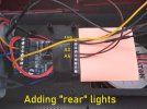
(The pink slip of paper is just there to make it easier to photograph the relevant cables.)
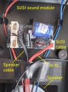
The only remaining cabling is for the Massoth S sound module (or any SUSI sound module). You can connect these directly to track power but generally I prefer to use the SUSI connection. If you are going to use SUSI you can remove the white and brown track power cables from the Massoth S, or just wrap them out of the way. Plug the 4-wire cable into the SUSI socket of the XL and the other end into the SUSI socket of the S, plug the loudspeaker cable into the S and job done. The space for the loudspeaker (70 mm 8 ohm 2 W) is in the chassis well.
Now put it back together, being careful not to trap any wires. When replacing screws, it's a good idea to place the screws in the hole, then turn the screwdriver as if to unscrew them, until you feel the screw drop into the existing groove. That way you don't cut a new groove in the plastic, which if you repeated several times might prevent the screw from biting.
Now put the loco on your programming track for testing. NEVER put a newly decoder installed loco onto powered track. If you have made a wiring error you may irreparably damage the decoder. ALWAYS put it on programming track first. If you can read and write CVs then you can be pretty confident there are no shorts in the wiring.
You need to tune the decoder to your preferences for address, speed, speed steps, etc so I won't go through those. The ones you will need to change to add the rear lights (connected to function outputs A3 and A4) are as follows:
CV 112 - A3+A4 dimming value - although the LEDs can handle full track voltage you may want to dim them a bit. I set this to 24 (out of 32) or 75% brightness.
CV 113 - A3 command - this is for the red lights at the front so you want these to come on when the loco is going backwards - I chose to use F7 to turn on rear lights so the value I needed was 7 + 64 (backwards only) = 71
CV 113 - A4 command - this is for the rear lights, which need to be on when the loco is going forwards. The value for this is (in my case) 7 + 128 (forwards only) = 135
CV 13 - Functions in Analog Mode - if you sometimes run your loco on analogue, and you want the red rear lights to come on then this CV lets you turn on selected decoder outputs when running on analogue. In this case we want A3 and A4 to be on, so the value for this is 4 (A3) + 8 (A4) = 12
To enable sound (as we are using the SUSI connection) all you need to do is set SUSI on in the XL decoder. By default it is set to LGB bus not SUSI bus.
CV 49 - Massoth Configuration - this controls various settings using bits, including whether or not back EMF is enabled (Massoth call this "load control") and the protocol for the bus. I didn't need load control so I set this CV to 16 (SUSI bus).
I won't go into the many settings for sound in the Massoth S sound decoder. If you have loaded the sound project for the BR 110 or any suitable diesel, then you can just use the defaults provided as a starting point. I prefer the "small diesel" project as it includes the triple horn sound for shunting, uncoupling sound and a generator sound, as well as the usual engine start-up and shutdown.
That's about it. Time for some testing.

They come as analogue DC models with 2 motors and directional lighting, but provide for upgrade to DCC, sound, and extra lighting options (red rear lights). There are PIKO upgrade options you can buy, or you can do your own thing. I prefer Massoth so I have used a Massoth XL decoder and a Massoth S sound module, mainly because I had a spare one. PIKO used to rebadge Massoth XL decoders as their own, so the earlier instructions they provide can be applied to installing the Massoth XL. For sound they used to rebadge the Uhlenbrock SUSI sound modules which are "plug and play", but more recently they have produced their own motor and sound decoders. I did however use their light options kit (#36016).
To open up the loco (i.e. remove the body shell), there are eight screws, four of which hold on the buffer beams which you then have to unclip as they have a slot and lug holding the body shell in place at the ends. These are larger screws, the other four are quite small and hard to locate, you have to swivel the bogies to access them. I think once these small screws are undone you could possibly leave them out as no way will the body separate once the buffer beams are locked in.


Once open you can remove the analogue circuit board (two diodes for the directional lighting!) making note of which wires go where, preferably labelling them before you remove them. Here's a rundown of the eight connections:
1 - track- (black)
2 - motor+ (blue)
3 - rear lights (yellow)
4 - unused
5 - +ve common (black)
6 - front lights (yellow)
7 - motor- (red)
8 - track+ (black)

Here's how they map to the nine Massoth XL connectors (right hand side):
A1 - unused
LI-H - rear lights (yellow)
M- - motor- (red)
GL- - track- (black)
GL+ - track+ (black)
M+ - motor+ (blue)
LI-V - front lights (yellow)
GRD - unused
+22 - +ve common (black)
Given that there are three black wires and two yellow wires there is scope for error! Be especially careful of the black wire for the +ve common, you don't want to be accidentally shoving track power into that connection. It is easy to identify the +ve common as it has resistors hidden in heat shrink to protect the LED lights from current overload.
That's the existing wires covered, now to add the "additional lighting" LEDs from accessory pack 36016. They are wired in pairs for front and back, with brown wires (-ve) and (more) black wires (+ve). The LED lights plug into the holes in the light harness at each end of the loco. There is a handy "two into one" short piece of cable that allows you to plug in the two +ve black wires into one, which makes it much easier to connect to the decoder.

You could plug these into the LI-V (front) and LI-H (rear) light connections on the XL, in reverse of the white directional lights, but that would mean the rear lights would always be on. This would not be prototypical as rear lights are only on if the loco is running as a light engine, or at the rear of a train. To make them selectable, I used the A3 and A4 outputs of the decoder. Here are the connections for the XL (left hand side):
+22 - +ve common (black)
LI-I - unused
A2 - unused
A3 - front lights (brown)
A4 - rear lights (brown)
A5 - unused
A6 - unused
K1 - unused
K2 - unused

(The pink slip of paper is just there to make it easier to photograph the relevant cables.)
The only remaining cabling is for the Massoth S sound module (or any SUSI sound module). You can connect these directly to track power but generally I prefer to use the SUSI connection. If you are going to use SUSI you can remove the white and brown track power cables from the Massoth S, or just wrap them out of the way. Plug the 4-wire cable into the SUSI socket of the XL and the other end into the SUSI socket of the S, plug the loudspeaker cable into the S and job done. The space for the loudspeaker (70 mm 8 ohm 2 W) is in the chassis well.

Now put it back together, being careful not to trap any wires. When replacing screws, it's a good idea to place the screws in the hole, then turn the screwdriver as if to unscrew them, until you feel the screw drop into the existing groove. That way you don't cut a new groove in the plastic, which if you repeated several times might prevent the screw from biting.
Now put the loco on your programming track for testing. NEVER put a newly decoder installed loco onto powered track. If you have made a wiring error you may irreparably damage the decoder. ALWAYS put it on programming track first. If you can read and write CVs then you can be pretty confident there are no shorts in the wiring.
You need to tune the decoder to your preferences for address, speed, speed steps, etc so I won't go through those. The ones you will need to change to add the rear lights (connected to function outputs A3 and A4) are as follows:
CV 112 - A3+A4 dimming value - although the LEDs can handle full track voltage you may want to dim them a bit. I set this to 24 (out of 32) or 75% brightness.
CV 113 - A3 command - this is for the red lights at the front so you want these to come on when the loco is going backwards - I chose to use F7 to turn on rear lights so the value I needed was 7 + 64 (backwards only) = 71
CV 113 - A4 command - this is for the rear lights, which need to be on when the loco is going forwards. The value for this is (in my case) 7 + 128 (forwards only) = 135
CV 13 - Functions in Analog Mode - if you sometimes run your loco on analogue, and you want the red rear lights to come on then this CV lets you turn on selected decoder outputs when running on analogue. In this case we want A3 and A4 to be on, so the value for this is 4 (A3) + 8 (A4) = 12
To enable sound (as we are using the SUSI connection) all you need to do is set SUSI on in the XL decoder. By default it is set to LGB bus not SUSI bus.
CV 49 - Massoth Configuration - this controls various settings using bits, including whether or not back EMF is enabled (Massoth call this "load control") and the protocol for the bus. I didn't need load control so I set this CV to 16 (SUSI bus).
I won't go into the many settings for sound in the Massoth S sound decoder. If you have loaded the sound project for the BR 110 or any suitable diesel, then you can just use the defaults provided as a starting point. I prefer the "small diesel" project as it includes the triple horn sound for shunting, uncoupling sound and a generator sound, as well as the usual engine start-up and shutdown.
That's about it. Time for some testing.

-
3
-
1
-
1
- Show all

