Any limitation on the length of the cat5e cable from the CS3+ to the 60881? I'm clutching at straws now... Tried different ports on the controller. Running out of options.
You had said that the 60881 to CS3+ connection is working, correct? Back in post #10 you said it was all working. I didnt catch it at the time but what 'Controlling Contact' setting are you referring to?
The track contacts come in pairs, and I was wondering if you have tried both contacts? In the 56 Massoth digital contacts that I have I did have 1 that just didnt work at all from the start and i had to replace it.
How long a cable connection between the 60881 and CS3+ do you have? I'm using a 10ft cable and it works just fine.
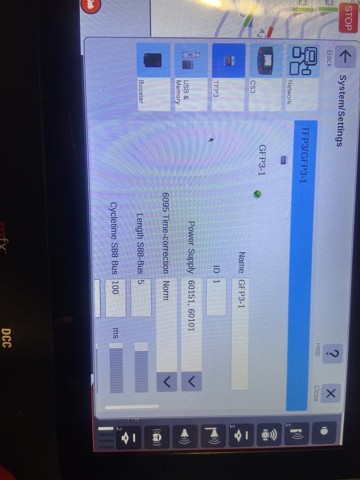
Do you have a pic of the whole setup? It might be helpful to see how its all connected together. The S88 need the RJ45 connected in a particular direction to the CS3. Then there is the System->System(Settings)->TFP3->Settings->Length S88-bus. What is that set to?