Installing a Mossoth eMotion XL in an LGB 23851 with decoder interface.

Mike Bett

Beer, G Gauge, Beer, Cricket, Beer.
14 Apr 2010
201
3
Fallbrook, California.
Country
United-States
Best answers
0
Country flag
I am in the process of putting an XL in my 23851 Mallet.
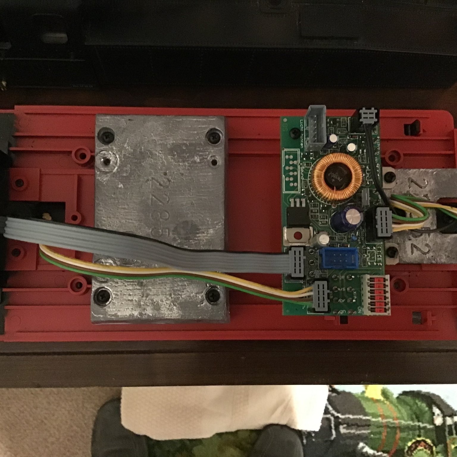
I am confused (for me easily) by the Massoth instruction booklet for connection to the LGB Decoder interface. I attach a picture of the interface in case it is different to what I think it is!

I have 2 LGB 55026 interface cables and the two cables included with the XL.
The engine previously had two LGB chips, now removed, one was faulty.

Please will someone give me simple instructions as to what connections are needed to be made from the interface to the XL board.
 

Attachments

  • 53C65A3A-EC4D-4F98-9F9B-FDE22462E688.jpeg
    53C65A3A-EC4D-4F98-9F9B-FDE22462E688.jpeg
    342.3 KB · Views: 0

phils2um

Phil S
11 Sep 2015
1,522
423
Ann Arbor, Michigan
Country
United-States
Best answers
0
Country flag
Here is how the XL is wired and connected to your decoder interface:

Screen Shot 2022-02-04 at 1.44.59 AM.png

Screen Shot 2022-02-04 at 2.01.41 AM.png
 
  • Like
Reactions: 1 user

Zerogee

Clencher's Bogleman
25 Oct 2009
17,362
1,724
North Essex
Best answers
0
Country flag
New XL decoder.jpg


Here's a pic of the installation of an XL into my Mallet, very similar to yours except that mine was the factory (serial) sound version... the main board in the loco is pretty much the same as your example, I think.

From this shot, you should be able to see the doubled-up sets of green/brown/white/yellow cables that connect to the motor and track terminals on the XL - I inserted the paired cables directly into the XL terminals, which works fine - though if I did one again I might connect each pair together into a "Y" joint and then just put the single wire into the terminal, as getting the twisted pair into a single terminal is a bit fiddly - and you don't want an odd wire strand coming loose and causing a short!
The 55026 interface cable goes into the board socket as shown, and the 6-way ribbon cables to the individual terminals on the XL as per the diagram in Phil's post above.

It is important that the six red DIP switches in the grey block (bottom right of the board in the pic above) are in the correct position as shown - but as your loco was already DCC fitted with the two old decoders, they should be correctly set already.

Like yours, my loco (bought second-hand from Germany) had a faulty factory-fitted DCC when I got it - in my case, not even a pair of 55020 chips, but a single 55020 and a 55030 motor booster board (which had failed). The 55030 was apparently a very short-lived stopgap way of boosting the output of a single old 55020 in order to run a two-motor loco - is seems to have been a bit rubbish and was quickly forgotten about by LGB, but they might still turn up on factory-DCC locos made around 1999-2000 or so, in the very early days of serial MTS1.

Hope that this, in conjunction with Phil's very useful diagrams, will help a bit?

Jon.
 
  • Like
Reactions: 1 user

Zerogee

Clencher's Bogleman
25 Oct 2009
17,362
1,724
North Essex
Best answers
0
Country flag
Just for general interest, this is the old 55020/55030 lash-up that LGB had factory-installed in the Mallet...

Mallet pic6-decoder.jpg

All kludged together with double-sided tape and a couple of decoder mounting clips, then stuffed into the smokebox!

Quickly ripped out and binned, then replaced with an XL which works beautifully, even with the old serial sound system.

Jon.
 

Mike Bett

Beer, G Gauge, Beer, Cricket, Beer.
14 Apr 2010
201
3
Fallbrook, California.
Country
United-States
Best answers
0
Country flag
Many thanks to both of you. Your diagrams, explanations and photos could not be clearer.
I can now proceed with confidence!
 

LGB333

Active Member
TRADER
15 Feb 2015
689
43
McLean Virginia
www.olddominionrailways.com
Best answers
0
Country flag
View attachment 295011


Here's a pic of the installation of an XL into my Mallet, very similar to yours except that mine was the factory (serial) sound version... the main board in the loco is pretty much the same as your example, I think.

From this shot, you should be able to see the doubled-up sets of green/brown/white/yellow cables that connect to the motor and track terminals on the XL - I inserted the paired cables directly into the XL terminals, which works fine - though if I did one again I might connect each pair together into a "Y" joint and then just put the single wire into the terminal, as getting the twisted pair into a single terminal is a bit fiddly - and you don't want an odd wire strand coming loose and causing a short!
The 55026 interface cable goes into the board socket as shown, and the 6-way ribbon cables to the individual terminals on the XL as per the diagram in Phil's post above.

It is important that the six red DIP switches in the grey block (bottom right of the board in the pic above) are in the correct position as shown - but as your loco was already DCC fitted with the two old decoders, they should be correctly set already.

Like yours, my loco (bought second-hand from Germany) had a faulty factory-fitted DCC when I got it - in my case, not even a pair of 55020 chips, but a single 55020 and a 55030 motor booster board (which had failed). The 55030 was apparently a very short-lived stopgap way of boosting the output of a single old 55020 in order to run a two-motor loco - is seems to have been a bit rubbish and was quickly forgotten about by LGB, but they might still turn up on factory-DCC locos made around 1999-2000 or so, in the very early days of serial MTS1.

Hope that this, in conjunction with Phil's very useful diagrams, will help a bit?

Jon.
Were you able to get the whistle and bell to activate with F Keys? I know some hobbyists who've installed Massoth XL decoders into their LGB locomotive's DCC Interface connectors who can't get the analog board to activate whistle/horn and bell with their F Keys. I have done a couple recently myself for customers and was able to get the F Keys to work but I'm using the Massoth DCC command station and Navigator which have both Parallel and Serial Mode control. My customers' DCC systems don't have Serial control, only Parallel Mode.
 
Last edited:

Zerogee

Clencher's Bogleman
25 Oct 2009
17,362
1,724
North Essex
Best answers
0
Country flag
Were you able to get the whistle and bell to activate with F Keys? I know some hobbyists who've installed Massoth XL decoders into their LGB locomotive's DCC Interface connectors who can't get the analog board to activate whistle/horn and bell with their F Keys. I have done a couple recently myself for customers and was able to get the F Keys to work but I'm using the Massoth DCC command station and Navigator which have both Parallel and Serial Mode control. My customers' DCC systems don't have Serial control, only Parallel Mode.

Like you, I use an all-Massoth system (1200Z and Navvies) and have had no trouble with control of the sounds on old LGB serial boards.
With different brands of DCC central stations that don't have the "legacy functions" of the serial mode option, then I guess it might be a problem...?

Jon.
 

Neil Robinson

Registered
24 Oct 2009
9,699
579
N W Leicestershire
Best answers
0
Country flag
Were you able to get the whistle and bell to activate with F Keys? I know some hobbyists who've installed Massoth XL decoders into their LGB locomotive's DCC Interface connectors who can't get the analog board to activate whistle/horn and bell with their F Keys. I have done a couple recently myself for customers and was able to get the F Keys to work but I'm using the Massoth DCC command station and Navigator which have both Parallel and Serial Mode control. My customers' DCC systems don't have Serial control, only Parallel Mode.
I'm some not surprised that some hobbyists have problems with serial sounds using parallel only control systems.
When I chipped my LGB/Aster Garratt I didn't want to make any irreversible changes. I fitted a Massoth XL decoder set to serial operation as my Piko DCC control system copes with both serial and analogue and the sound board is serial only. However I had fitted a Massoth fan driven smoke unit that doesn't accept serial activation. Solution, set the smoke unit to a different address and use this, in parallel mode, to turn the smoke on and off.
 
  • Like
Reactions: 1 user

Mike Bett

Beer, G Gauge, Beer, Cricket, Beer.
14 Apr 2010
201
3
Fallbrook, California.
Country
United-States
Best answers
0
Country flag
My sound system is the European LGB sounds box. It is fitted into the carriage immediately behind the engine and powered, as are the lights, from the engines rear take off plug.
No problems at all.
 

Andrew_au

Registered
12 Nov 2021
146
1
51
Sydney, Australia
Best answers
0
Country flag
Were you able to get the whistle and bell to activate with F Keys? I know some hobbyists who've installed Massoth XL decoders into their LGB locomotive's DCC Interface connectors who can't get the analog board to activate whistle/horn and bell with their F Keys
The Massoth chips offer a "fast-pulse" mode that is supposed to be able to drive the LGB serial sound interface using standard F keys. I've found two problems with it using an LGB 28002:
  • to enable fast pulse mode you also need to enable serial compatibility mode, which is silly. Serial compatibility allows a serial handset to trigger standard F keys. Fast pulse mode allows standard F keys to trigger A1 as if they were serial. Both at the same time doesn't make sense.
  • the pulse rate is fast. Hooked up to a lamp, it's slow enough that I can see each toggle with the naked eye, but faster than I can count in my head. Unfortunately, some of the older systems prefer the toggles to be at least 0.25s (approx) apart or they get missed.
Whether it works will depend on whether the built in sound interface can handle the pulse rate. If not, you'll need to get the handset to trigger F1 toggles, which are much slower.


Explanation of why enabling "serial compatibility" and "fast pulse" on a single decoder is not useful.

Background:
  • A standard handset can instruct the decoder to set F1 .. F8. Note that this is an explicit 'set' or 'clear', not a toggle.
  • A "serial mode" handset maps F1 .. F8 into that many toggles of F1. Note that this is stateless. I don't "set" or "clear" (say) F4. I just toggle F1 4 times and the peripheral decides what "F4 has been pressed" means for its state. Sometimes this is an on/off toggle, other times it just plays a single sound to completion.
  • The older LGB devices attach a "smart" peripheral to decoder output A1 (driven by F1). This peripheral counts toggles of A1 and translates that into operations. 1 toggle for operation 1, 8 for operation 8. The idea is that the handset sends serial mode (F1 toggles), the decoder changes A1 accordingly, and the peripheral (typically a sound/smoke unit) interprets that as commands.
(Note: using F1-F8 to refer to the DCC signals, and A1-A8 to refer to the output pins on the decoder)

Serial compatibility mode on a decoder allows "serial" F1-F8 (i.e. some number of F1 toggles) to drive actual A1-A8.
  • This useful if you have a serial handset and want it to drive standard decoder outputs. Alternative - get a better handset.
Fast pulse mode on a decoder allows actual F1-F8 to drive A1 as if you toggled F1 (i.e. serial mode). Note that this loses the idea of set/clear (e.g. F5-on and F5-off both become F5-event, with On or Off determined by the internal state of the peripheral).
  • This is useful if you have an old loco peripheral that needs to be driven by a decoder that doesn't support serial mode.
  • In theory, it also allows serial mode commands to be played out much more quickly, as you can just toggle A1 rather than wait for F1-on, F1-off, etc to be transmitted over the rails. That assumes that fast toggling won't confused the peripheral (oops!).
Why are they not useful together?
  • Serial mode allows a serial handset to drive standard mode outputs
  • Fast pulse mode allows a standard handset to drive a single serial output
So the two modes essentially solve opposite problems. The problem with enabling them both is that, in compatibility mode, serial mode inputs no longer drive F1/A1. Instead, they are converted into standard F1-F8 operations which then (hopefully) get converted back into serial pulses out A1. Since you can't use A2-A8 sensibly when you have a serial mode peripheral using fast pulse mode (as it captures F2-F8 and synthesises them out A1), there's no benefit in converting serial pulses into F1-F8 only to convert them back into pulses - it just adds extra things to go wrong on the decoder.
 

muns

Well-Known Member
Staff member
GSC Moderator
24 Oct 2009
5,718
130
Southampton, U.K.
www.gardenrailoutlet.co.uk
Best answers
0
Country flag
The problem with enabling them both is that, in compatibility mode, serial mode inputs no longer drive F1/A1. Instead, they are converted into standard F1-F8 operations which then (hopefully) get converted back into serial pulses out A1. Since you can't use A2-A8 sensibly when you have a serial mode peripheral using fast pulse mode (as it captures F2-F8 and synthesises them out A1), there's no benefit in converting serial pulses into F1-F8 only to convert them back into pulses - it just adds extra things to go wrong on the decoder.
Are you sure that this is correct? Im sure that when (for example) A2 is mapped to F2, pressing F2 will activate(toggle) A2 and the A1 chain fire 2 pulses.
 

PhilP

G Scale, 7/8th's, Electronics
5 Jun 2013
33,638
3,532
Nottingham
Best answers
0
Country flag
Are you sure that this is correct? Im sure that when (for example) A2 is mapped to F2, pressing F2 will activate(toggle) A2 and the A1 chain fire 2 pulses.
That is as I understand it..
As an example :
Firebox light on A2 output switched on AND two-pulses of F1, to trigger older serial soundcard, for coal shovelling.
 

Zerogee

Clencher's Bogleman
25 Oct 2009
17,362
1,724
North Essex
Best answers
0
Country flag
A lot of the above is "all geek to me". ;)
All I can tell you from personal experience is that when I did my Mallet as described and pictured above, all I did was to wire the XL in, choose the "S" rather than "P" mode when setting up the loco profile on the Navvy, and it all just worked... :)

Jon.
 

palmerston

trains
24 Oct 2009
571
14
Netherlands, near Aachen ;-)
Best answers
0
Country flag

Ralphmp

Registered
6 Jan 2010
1,640
228
72
Herts
Country
England
Best answers
0
Country flag
Not sure why but I get a Safari can’t show this page message (URL can’t be shown) when trying to access the link. Also, I’d need to check, but when I installed an XL in one of my older mallets I don’t recall making any parallel to serial changes and everything just worked.
 

LGB333

Active Member
TRADER
15 Feb 2015
689
43
McLean Virginia
www.olddominionrailways.com
Best answers
0
Country flag
Here's another way to activate the old LGB factory sound boards when convert the locomotive to DCC. This is an LGB Uintah that the customer wanted me to retain the sound instead of installing a DCC sound decoder to replace all the factory electronics. So I removed the original circuit board and installed a Massoth XL Driving/Function Decoder. For Whistle and Bell activation using F1 and F2 Keys, I installed two ESU 51963 12-16v. Miniature Relays, photos #1 and #2, wired to the decoder's Terminals A3 and A4 and with CV114 and 116 set to "65 Monoflop." These outputs were wired to the sound board's whistle and bell reed switch input socket shown in photo # 3 and #4.. I used F1 at Terminal A1 for Sound On/Off and F7 at Terminal A5for smoker On/Off using an 18v. smoker to replace the factory 5v. unit. I set the decoder's output voltage to the factory sound board for 11 volts. At first I didn't receive the automatic sounds, such as starting whistle, and other standing noises, but after lowing the voltage to the sound board all the automatic sounds work great. Photos of the installation are below. The relay sells for $4 on my Website.


ESU Relay Uintah 1.JPGESU Relay Uintah 2.JPGESU Relay Uintah 3.JPGESU RElay Uintah Install 4.jpgESU Relay Uintah Sound Wiring Diagram.jpgESU Miniature Relay.jpg